作者:順哥
email:palmbear@gmail.com
資料來源:
1.image2cpp
2.| ESP32 教學 | MicroPython | I2C OLED Image 顯示圖像 | 209 |
3.SSD1306.py
Table of Contents
[TOC]
前言
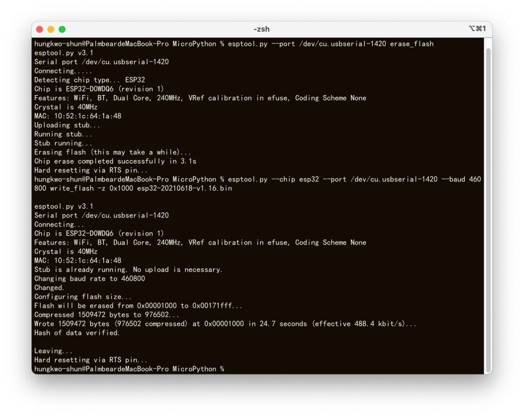
測試在 macOS Monterey 12.4 環境,使用 Micropython 在 ESP32 用 SSD1306 OLED 顯示 image 圖形。
Step 1:使用的圖形
在 google網站搜尋一張看起來順眼,個人使用無版權的黑色的熊熊圖(png檔),就用這張圖來做測試,這張圖的原始尺寸為 “981 x 562″。
網頁畫面:
Step 2:將圖形轉換成 byte arrays
因為在macOS上找不到適當軟體可以使用,在 google網站上找到這個
image2ccp
這個網站可以將 image 轉換為 byte arrays(或將您的 byte arrays 轉換回 image),然後給 OLED 顯示出來。
網頁畫面:
- 選擇圖形 Select image:
點選「選擇檔案」,上傳圖形檔。
網頁畫面:
- 圖形設定 image Settings:
在「畫布尺寸」 Canvas size(s) 欄位中,填入 OLED 的像數規格,我使用 “128 x 64″ ,所以在這裡我們填入 “128″ 及 “64″ ,圖形的原始尺寸為 “981 x 562″,這個網站可以將圖形直接轉成我們需要的大小。
接下來選擇 “stretch to fill canvas" 「拉伸填充畫布」。
網頁畫面:
- 圖形預覽 Preview:
隨即就會在「圖形預覽」Preview,看到圖形。 - 輸出 Output:
在「代碼輸出格式」"Code output format" 欄位中,填入 “plain bytes" ,
接下來在「繪製模式」"Draw mode" 欄位中,填入 “Vertical – 1 bit per pixel" ,
最後按下 “Generate code" 擷取碼,並將16進位的碼 Copy 下來。
網頁畫面:
Step 3:測試程式碼
我使用 資料來源2 的程式碼,SSD1306 module 使用 資料來源3 ,並依照自己的ESP32接腳,改用SoftI2C,我的程式碼如下:
from machine import Pin, SoftI2C #從machine 匯入 Pin, SoftI2C
import ssd1306 #匯入 ssd1306模組
import framebuf #匯入 fram3buf模組

i2c = SoftI2C(scl=Pin(22), sda=Pin(21), freq=400000) # 建立 i2c 物件

oled=ssd1306.SSD1306_I2C(128, 64, i2c) #建立 oled096 物件,第 1 個參數與第 2 個參數設定為 OLED 模組的像素,第 3 個參數為 I2C 的物件名稱

# img64 是一個 bytearrays 的列表(List)
img64 = [
0xff, 0xff, 0xff, 0xff, 0xff, 0xff, 0xff, 0xff, 0xff, 0xff, 0xff, 0xff, 0xff, 0xff, 0x7f, 0x7f,
0x3f, 0x1f, 0x1f, 0x0f, 0x07, 0x07, 0x07, 0x03, 0x03, 0x01, 0x01, 0x01, 0x01, 0x01, 0x00, 0x00,
0x00, 0x00, 0x00, 0x00, 0x00, 0x00, 0x00, 0x00, 0x00, 0x00, 0x00, 0x00, 0x01, 0x01, 0x01, 0x01,
0x01, 0x01, 0x01, 0x01, 0x03, 0x03, 0x03, 0x03, 0x03, 0x03, 0x03, 0x03, 0x03, 0x03, 0x07, 0x07,
0x07, 0x07, 0x07, 0x07, 0x07, 0x07, 0x07, 0x07, 0x07, 0x03, 0x03, 0x03, 0x01, 0x01, 0x01, 0x01,
0x01, 0x01, 0x01, 0x01, 0x03, 0x03, 0x03, 0x03, 0x07, 0x07, 0x07, 0x07, 0x0f, 0x0f, 0x0f, 0x1f,
0x1f, 0x1f, 0x1f, 0x1f, 0x1f, 0x1f, 0x1f, 0x1f, 0x1f, 0x3f, 0x3f, 0x3f, 0x3f, 0x3f, 0x7f, 0x7f,
0x7f, 0x3f, 0x3f, 0x7f, 0xff, 0xff, 0xff, 0xff, 0xff, 0xff, 0xff, 0xff, 0xff, 0xff, 0xff, 0xff,
0xff, 0xff, 0xff, 0xff, 0xff, 0xff, 0xff, 0xff, 0x3f, 0x1f, 0x07, 0x03, 0x01, 0x00, 0x00, 0x00,
0x00, 0x00, 0x00, 0x00, 0x00, 0x00, 0x00, 0x00, 0x00, 0x00, 0x00, 0x00, 0x00, 0x00, 0x00, 0x00,
0x00, 0x00, 0x00, 0x00, 0x00, 0x00, 0x00, 0x00, 0x00, 0x00, 0x00, 0x00, 0x00, 0x00, 0x00, 0x00,
0x00, 0x00, 0x00, 0x00, 0x00, 0x00, 0x00, 0x00, 0x00, 0x00, 0x00, 0x00, 0x00, 0x00, 0x00, 0x00,
0x00, 0x00, 0x00, 0x00, 0x00, 0x00, 0x00, 0x00, 0x00, 0x00, 0x00, 0x00, 0x00, 0x00, 0x00, 0x00,
0x00, 0x00, 0x00, 0x00, 0x00, 0x00, 0x00, 0x00, 0x00, 0x00, 0x00, 0x00, 0x00, 0x00, 0x00, 0x00,
0x00, 0x00, 0x00, 0x00, 0x00, 0x00, 0x00, 0x00, 0x00, 0x00, 0x00, 0x00, 0x00, 0x00, 0x00, 0x00,
0x00, 0x00, 0x00, 0x00, 0x00, 0x01, 0x01, 0x03, 0x03, 0x07, 0x2f, 0x7f, 0xff, 0xff, 0xff, 0xff,
0xff, 0xff, 0xff, 0xff, 0xff, 0x3f, 0x07, 0x00, 0x00, 0x00, 0x00, 0x00, 0x00, 0x00, 0x00, 0x00,
0x00, 0x00, 0x00, 0x00, 0x00, 0x00, 0x00, 0x00, 0x00, 0x00, 0x00, 0x00, 0x00, 0x00, 0x00, 0x00,
0x00, 0x00, 0x00, 0x00, 0x00, 0x00, 0x00, 0x00, 0x00, 0x00, 0x00, 0x00, 0x00, 0x00, 0x00, 0x00,
0x00, 0x00, 0x00, 0x00, 0x00, 0x00, 0x00, 0x00, 0x00, 0x00, 0x00, 0x00, 0x00, 0x00, 0x00, 0x00,
0x00, 0x00, 0x00, 0x00, 0x00, 0x00, 0x00, 0x00, 0x00, 0x00, 0x00, 0x00, 0x00, 0x00, 0x00, 0x00,
0x00, 0x00, 0x00, 0x00, 0x00, 0x00, 0x00, 0x00, 0x00, 0x00, 0x00, 0x00, 0x00, 0x00, 0x00, 0x00,
0x00, 0x00, 0x00, 0x00, 0x00, 0x00, 0x00, 0x00, 0x00, 0x00, 0x00, 0x00, 0x00, 0x00, 0x00, 0x00,
0x00, 0x00, 0x00, 0x00, 0x00, 0x00, 0x00, 0x00, 0x00, 0x00, 0x00, 0x00, 0x00, 0x81, 0xc3, 0xf7,
0xff, 0xff, 0xff, 0xff, 0xc1, 0x00, 0x00, 0x00, 0x00, 0x00, 0x00, 0x00, 0x00, 0x00, 0x00, 0x00,
0x00, 0x00, 0x00, 0x00, 0x00, 0x00, 0x00, 0x00, 0x00, 0x00, 0x00, 0x00, 0x00, 0x00, 0x00, 0x00,
0x00, 0x00, 0x00, 0x00, 0x00, 0x00, 0x00, 0x00, 0x00, 0x00, 0x00, 0x00, 0x00, 0x00, 0x00, 0x00,
0x00, 0x00, 0x00, 0x00, 0x00, 0x00, 0x00, 0x00, 0x00, 0x00, 0x00, 0x00, 0x00, 0x00, 0x00, 0x00,
0x00, 0x00, 0x00, 0x00, 0x00, 0x00, 0x00, 0x00, 0x00, 0x00, 0x00, 0x00, 0x00, 0x00, 0x00, 0x00,
0x00, 0x00, 0x00, 0x00, 0x00, 0x00, 0x00, 0x00, 0x00, 0x00, 0x00, 0x00, 0x00, 0x00, 0x00, 0x00,
0x00, 0x00, 0x00, 0x00, 0x08, 0x38, 0xf8, 0xf8, 0xfc, 0xfc, 0xfc, 0xfc, 0xfc, 0xfc, 0xfe, 0xfe,
0xfe, 0xfe, 0xfe, 0xff, 0xff, 0xff, 0xff, 0xff, 0xfe, 0xfe, 0xff, 0xff, 0xff, 0xff, 0xff, 0xff,
0xff, 0xff, 0xff, 0xff, 0xff, 0xfe, 0xfc, 0xfc, 0x3c, 0x00, 0x00, 0x00, 0x00, 0x00, 0x00, 0x00,
0x00, 0x00, 0x00, 0x00, 0x00, 0x00, 0x00, 0x00, 0x00, 0x00, 0x00, 0x00, 0x00, 0x00, 0x00, 0x00,
0x00, 0x00, 0x00, 0x00, 0x80, 0x80, 0x80, 0x80, 0x80, 0x80, 0x80, 0x80, 0x80, 0x80, 0x80, 0x80,
0x80, 0x80, 0x80, 0xc0, 0xc0, 0x80, 0xc0, 0xc0, 0xc0, 0xe0, 0xe0, 0xe0, 0x20, 0x00, 0x00, 0x00,
0x00, 0x00, 0x00, 0x00, 0x00, 0x00, 0x00, 0x00, 0x00, 0x00, 0x00, 0x00, 0x00, 0x00, 0x00, 0x00,
0x00, 0x80, 0xc0, 0xf0, 0x80, 0x00, 0x00, 0x00, 0x00, 0x00, 0x00, 0x00, 0x00, 0x00, 0x00, 0x00,
0x00, 0x00, 0x00, 0x00, 0x00, 0x00, 0x01, 0x03, 0x0f, 0x3f, 0x7f, 0xff, 0xff, 0xff, 0xff, 0xff,
0xff, 0xff, 0xff, 0xff, 0xff, 0xff, 0xff, 0xff, 0xff, 0xff, 0xff, 0xff, 0xff, 0xff, 0xff, 0xff,
0xff, 0xff, 0x3f, 0x1f, 0x0f, 0x07, 0x03, 0x00, 0x00, 0x00, 0x00, 0x00, 0x00, 0x00, 0x00, 0x00,
0x00, 0x00, 0x00, 0x00, 0x00, 0x00, 0x00, 0x00, 0x00, 0x00, 0x00, 0x00, 0x00, 0x00, 0x00, 0x00,
0x00, 0x00, 0xe0, 0xfe, 0xff, 0xff, 0xff, 0xff, 0xff, 0xff, 0xff, 0xff, 0xff, 0xff, 0xff, 0xff,
0xff, 0xff, 0xff, 0xff, 0xff, 0xff, 0xff, 0xff, 0xff, 0xff, 0xff, 0x1f, 0x02, 0x00, 0x00, 0x00,
0x00, 0x00, 0x00, 0x00, 0x00, 0x00, 0x00, 0x00, 0x00, 0x00, 0x00, 0x00, 0x00, 0x80, 0xf0, 0xfc,
0xfc, 0xff, 0xff, 0xff, 0xff, 0xff, 0xfc, 0xf8, 0xf8, 0xf0, 0xe0, 0xc0, 0x80, 0x00, 0x00, 0x00,
0x00, 0x00, 0x00, 0x00, 0x00, 0x00, 0x00, 0x00, 0x00, 0x00, 0x00, 0x01, 0x03, 0x07, 0x1f, 0x3f,
0x7f, 0x3f, 0x7f, 0x7f, 0x7f, 0xff, 0xff, 0xff, 0xff, 0xff, 0xff, 0xff, 0xff, 0xff, 0xff, 0xff,
0xc1, 0x80, 0x00, 0x00, 0x00, 0x00, 0x00, 0x00, 0x00, 0x00, 0x00, 0x00, 0x00, 0x00, 0x80, 0xc0,
0xc0, 0xe0, 0xf0, 0xf8, 0x00, 0x00, 0x00, 0x00, 0x00, 0x00, 0x00, 0x00, 0x00, 0x00, 0x00, 0x00,
0x00, 0x00, 0xff, 0xff, 0xff, 0xff, 0xff, 0xff, 0xff, 0xff, 0xff, 0xff, 0xff, 0xff, 0xff, 0xff,
0xff, 0xff, 0xff, 0xff, 0xff, 0xff, 0xff, 0xff, 0xff, 0xff, 0xff, 0x01, 0x00, 0x00, 0x00, 0x00,
0x00, 0x00, 0x00, 0x00, 0x00, 0x00, 0x00, 0x00, 0x00, 0x00, 0xc0, 0xfc, 0xfe, 0xff, 0xff, 0xff,
0xff, 0xff, 0xff, 0xff, 0xff, 0xff, 0xff, 0xff, 0xff, 0xff, 0xff, 0xff, 0xff, 0xff, 0xff, 0xff,
0xfe, 0xf8, 0xf8, 0xf8, 0xf8, 0xf0, 0xf8, 0xf8, 0xf0, 0xf0, 0xf0, 0xf0, 0xf0, 0xf0, 0xf0, 0xf0,
0xf0, 0xf0, 0xf0, 0xf0, 0xf8, 0xfc, 0xfd, 0xff, 0xff, 0xff, 0xff, 0xff, 0xff, 0xff, 0xff, 0xff,
0xff, 0xff, 0xfc, 0x80, 0x00, 0x00, 0x00, 0x00, 0x00, 0x00, 0x00, 0x00, 0x00, 0x00, 0x01, 0x03,
0x87, 0x9f, 0xff, 0xff, 0xfc, 0xf8, 0xf8, 0xf0, 0xf0, 0xf0, 0xf0, 0xf0, 0xf0, 0xf0, 0xf0, 0xf0,
0xf0, 0xf0, 0xf0, 0xf8, 0xf9, 0xff, 0xff, 0xff, 0xff, 0xff, 0xff, 0xff, 0xff, 0xff, 0xff, 0xff,
0xff, 0xff, 0xff, 0xff, 0xff, 0xff, 0xff, 0xff, 0xff, 0xff, 0xfd, 0xf0, 0xf0, 0xe0, 0xe0, 0xe0,
0xe0, 0xe0, 0xe0, 0xe0, 0xe0, 0xe0, 0xe0, 0xc0, 0xc0, 0xc0, 0xc0, 0xc1, 0xc1, 0xc1, 0xc3, 0xc3,
0xe7, 0xdf, 0xff, 0xff, 0xff, 0xff, 0xff, 0xff, 0xff, 0xff, 0xff, 0xff, 0xff, 0xff, 0xff, 0xff,
0xff, 0xff, 0xff, 0xff, 0xff, 0xff, 0xff, 0xff, 0xff, 0xff, 0xff, 0xff, 0xff, 0xff, 0xff, 0xff,
0xff, 0xff, 0xff, 0xff, 0xff, 0xff, 0xff, 0xff, 0xff, 0xff, 0xff, 0xff, 0xff, 0xff, 0xff, 0xff
]

img064b = bytearray(img64)  # 將 img64 轉成 bytearray 型態,並取名 img64b
imgbuf=framebuf.FrameBuffer(img064b,128,64,framebuf.MONO_VLSB) #framebuf 第 1 個參數為影像資料的 bytearray名稱,第 2、3 個參數是影像的寬度與高度,第 4 個參數是像素形式與排列,MONO_VLSB 是指 單色+垂直+LSB
oled.blit(imgbuf, 0, 0) #blit方法,是將imgbuf 物件,由指定的 X,Y 位置,依序開始填入 OLED 記憶體
oled.invert(1) #以反白螢幕方式顯示圖形畫面
oled.show() #顯示螢幕畫面
程式說明
- 因為 framebuf 使用的資料型態是 bytearray,所以將 img64 轉成 bytearray 型態,並取名 img64b。
- 我們在轉檔時時是採用單色與垂直方向排列(Vertical)的方式存檔,所以預設轉出陣列就是 1btye 會有 8 像素,資料排列也就照著直線方式一條一條轉換,img64 原始資料共有 1024 個 bytes,換算成像素也就是1024×8=8192個像素,與我們OLED 的像素128*64=8192 Pixel 是相符的。
- mgbuf 為新建立的 framebuf 物件,framebuf 第 1 個參數為影像資料的 byte 序列,第 2、3 個參數分別為影像的寬度與高度,第 4 個參數就是像素形式與排列,MONO_VLSB 是指 單色+垂直+LSB(如果是其他形式可以填入framebuf.MONO_HLSB、framebuf.RGB565、framebuf.GS4_HMSB等。
- blit 這個方法也是源自 framebuf,將建立好的 imgbuf 物件,由指定的 X,Y 位置,依序開始填入 OLED 記憶體內。
Micropython framebuf 模組的官方說明
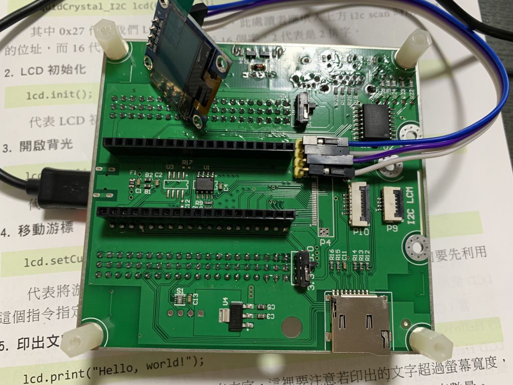
成果
完成畫面:
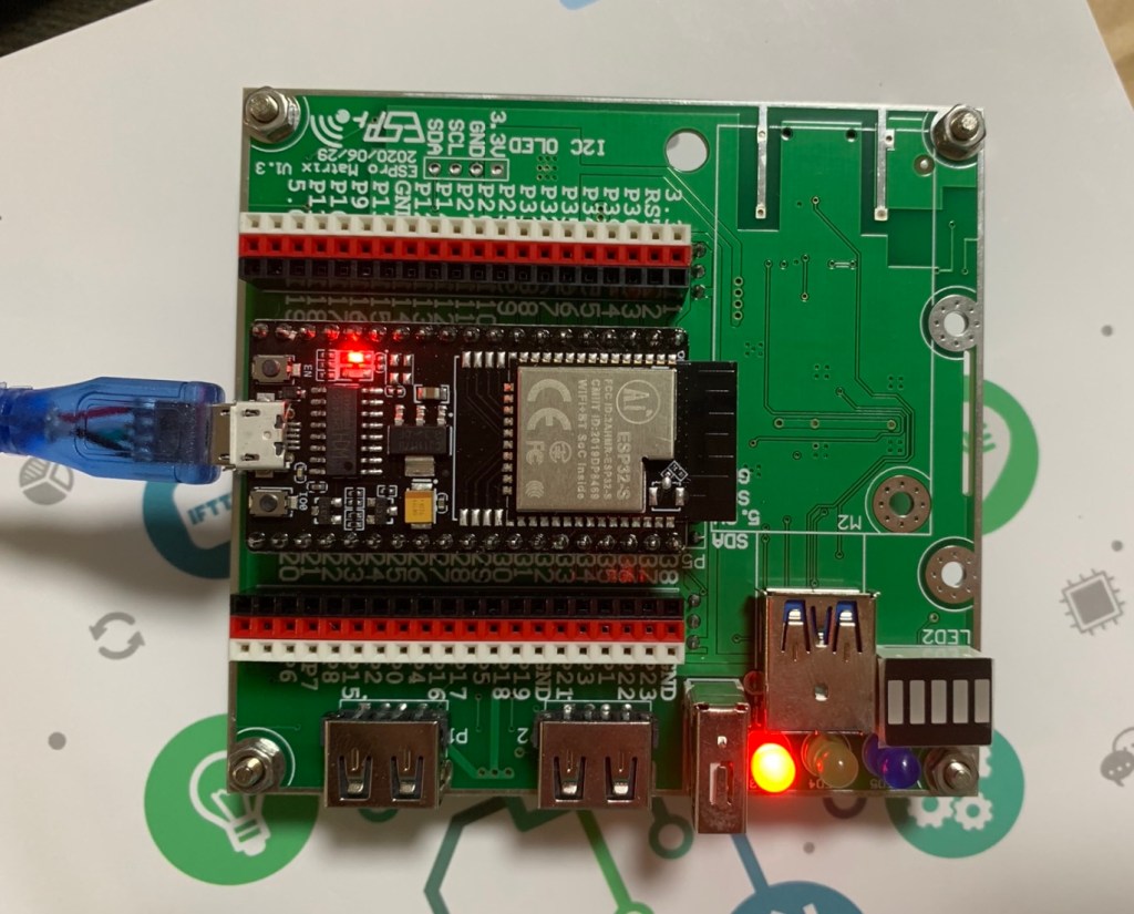
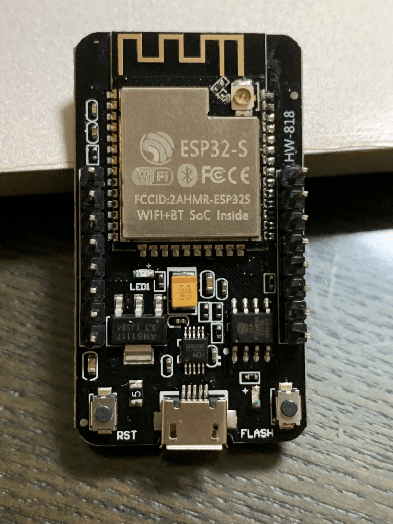
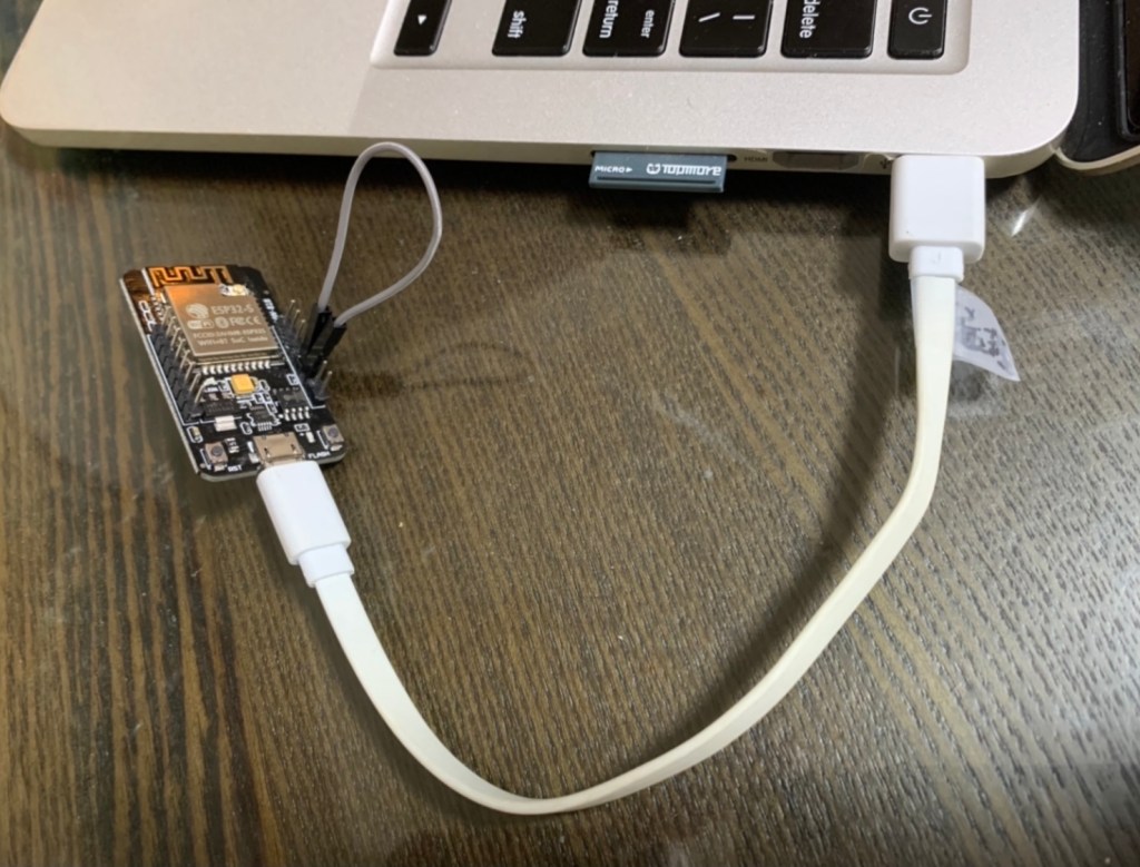
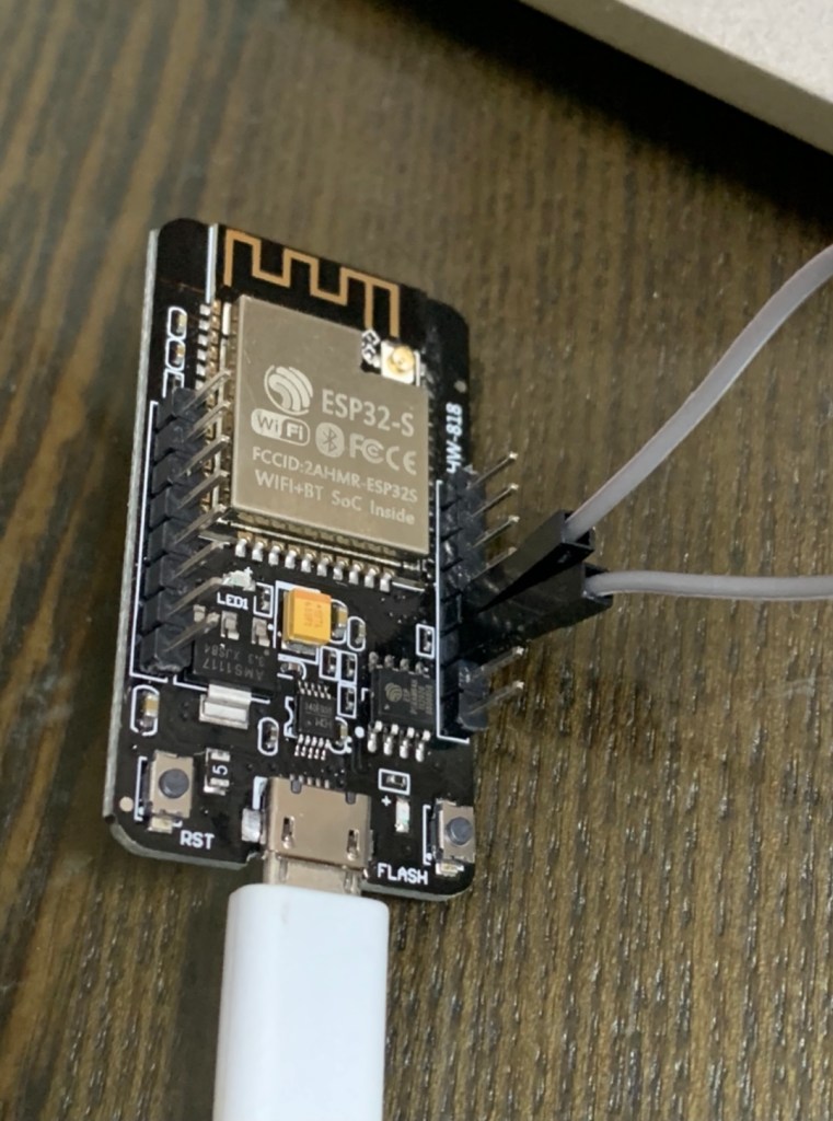
我使用的硬體: